Design and Installation Considerations for solar Energy Storage Systems
Design and Installation Considerations for Photovoltaic Energy Storage Systems
|、 Pre-Design Considerations
1、Demand Analysis and System Capacity Design
* Load Matching and Redundancy: Precisely calculate user load characteristics (e.g., motor startup surge currents), with inverter capacity reserved by at least 30% to handle instantaneous power demands.
* Energy Storage Configuration: Design capacity at 1.5-2 times the average daily electricity consumption, adjusting photovoltaic array tilt angle based on the worst-case solar radiation (typically winter) by increasing 2°–8° over local latitude to enhance winter efficiency.
* Battery Selection: Prioritize lithium iron phosphate (LFP) batteries (cycle life ≥6,000 cycles) or lead-carbon batteries (low-cost scenarios); sodium-ion batteries are recommended for high-temperature regions (cost reduction: 30–40%
2、Environmental Adaptation Design
* High-Temperature and Dust Resistance: Use dust-proof and heat-dissipating designs for components and storage equipment. Battery compartments must have ≥100mm ventilation gaps and high-temperature alarms.
* Grid Compatibility: Adopt grid-forming inverters or virtual synchronous machine (VSM) technology to enhance frequency and voltage stability in weak African grids.
* Wind and Earthquake Resistance: Ensure brackets meet local maximum wind speeds (≥35m/s) and seismic standards. Use specialized clamps for corrugated roofs and chemical anchors for concrete foundations
3、Localization and Cost Optimization
Modular Layout: Use AC/DC integrated systems to shorten installation cycles and reserve 20% capacity for future expansion
||、Photovoltaic Panel Installation (Adapted for African High-Temperature and Dusty Environments)
1、Site Selection and Bracket Design
* Anti-Shading Optimization: Ensure ≤5% shadow coverage during 9 AM–3 PM on the winter solstice. Component spacing should be 1.5 times the height (e.g., 3m spacing for 2m-high brackets).
* Corrosion Resistance and Load-Bearing: Use galvanized steel or aluminum alloy brackets with chemical anchors in concrete foundations. Apply waterproof adhesive for corrugated roofs.
* Heat Dissipation: Maintain ≥100mm gaps between components and roofs/grounds. Double-glass panels reduce backside temperatures by 5–8°C.
2、Installation Specifications
* Mounting Methods: Prefer clamping blocks (bolt torque: 14–20N·m). Secure edge clamps first, then center components. Avoid impacts or stepping on panels.
* Electrical Connections: Connect "+" of the front panel to "−" of the rear panel in series. Use diagonal pliers to trim cable ties and confirm connectors with an audible "click".
Grounding: Use 12AWG copper wires to bridge adjacent grounding holes. Ground resistance ≤4Ω; multi-point connections for lightning protection.
3、Maintenance Adaptations
* Cleaning Frequency: Clean monthly in dusty areas (soft cloth + neutral detergent) to prevent 20% efficiency loss.
* Extreme Weather Protection: Check drainage holes pre-rainy season and inspect sealants post-sandstorms
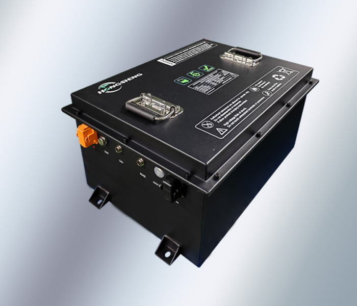
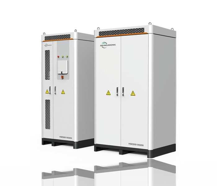
|||、Energy Storage System Installation (LFP Battery Focus)
1、LFP Battery Selection and Configuration
* Capacity Calculation: Size based on 1.5–2 times daily consumption, optimized for low solar periods (e.g., African dry season).
* High-Temperature Adaptation: Use models with cycle life ≥6,000 cycles (operating temperature: 0–60°C). Equip battery compartments with liquid cooling or forced ventilation (airflow ≥0.5m/s).
2、Safety Requirements
* Independent Battery Room: Install away from crowds/open flames, with ≥300kg/m² load capacity, explosion-proof lighting, and fireproof materials (fire resistance ≥2 hours).
* Mounting and Heat Dissipation: Maintain ≥50mm spacing between battery groups, add insulation pads under trays, and monitor SOC/temperature via BMS.
* Lightning Protection and Grounding: Multi-point grounding for battery enclosures; shielding layers grounded at single points, complying with IEC 61643.
3、System Integration Optimization
* Modular Design: Allow 20% capacity expansion and integrate diesel generators for grid instability scenarios.
* Smart Dispatch: Use EMS to align with peak/off-peak tariffs (e.g., South Africa), prioritizing nighttime discharge for 40–50% cost savings.
4、LFP Battery-Specific Requirements
* BMS Functions: Monitor cell resistance deviation (≤5mV), temperature (sensor spacing ≤20cm), and programmable charge/discharge thresholds (e.g., SOC 20–90%). Implement short-circuit protection (response ≤50ms) and thermal runaway alerts.
* Cycle Life Management: Use shallow discharge (DoD 80%) to extend cycles to 8,000. Perform monthly balancing (voltage deviation ≤0.1V) and quarterly health checks
IV、 Inverter Requirements (Adapted for African Weak Grids)
1、Performance Parameters
* Wide Voltage Input: DC 150–1,000V tolerance for aging components and shading.
* Weak Grid Support: Grid-forming inverters (e.g., Huawei 150K series) with VSM, THD ≤3%, and 100% unbalanced load support.
2、Smart Features
* MPPT Optimization: Dynamic efficiency ≥99.8%, multi-peak tracking for shaded scenarios.
* Remote Monitoring: Integrate MBUS PLC communication to reduce wiring costs by 30%.
3、Protection Standards
Environmental Tolerance: IP65 dust/water resistance, operating range: −25°C–60°C, with PID recovery for high humidit
V、 Installation Phase Summary
1、Site and Safety Measures
* Indoor Installation: Near power rooms (≤100m), ventilated, load ≥300kg/m².
* Outdoor Installation: Elevate foundations against flooding, use anti-corrosion materials, and maintain ≥1.5m safety zones.
* Lightning Protection: Ground resistance ≤4Ω, integrated with building grounding systems.
2、Equipment Installation Standards
* PV Components: Ensure no shading, spacing at 1.5× height, and waterproof junction boxes.
* Battery Groups: Secure on dedicated trays, maintain ≥50mm spacing, and monitor via BMS.
* Cabling: Separate DC/AC cables, waterproof conduits, and insulated terminals.
3、Safety and Commissioning
* Professional Teams: Certified personnel, safety barriers for heights, and weather restrictions.
Testing: Simulate grid failures and battery over-discharge pre-operation, verify inverter anti-islanding response ≤0.02s.